C&L MAF Meter
In 2002, with the exhaust end of the car's I/O bottlenecks
reasonably well squared away, I began looking critically at the intake components. The first thing
to be replaced was the
stock MAF meter. It wasn't yet a restriction, but I was planning on having the
intake ported, and that meant the stock meter had to go. I picked up a C&L
80mm kit and installed it. In addition to the meter, the kit included a large K&N filter and heat
shield. Installation was very simple, and took only about 15
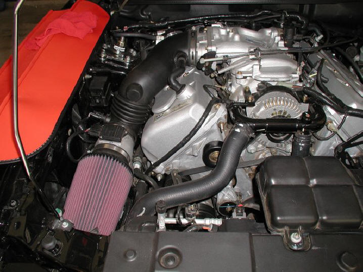
minutes. Below is a photo of the C&L prior to fastening the air
filter's heat shield in place:
NOTE: Installation of the Kenne-Bell twin-screw kit
required the removal of this upgrade.
TECH TIP: Although I believe the C&L MAF meter offers better air flow than the OEM meter,
the C&L possesses certain design deficiencies that must be overcome to obtain optimum performance in a '99 or '01 Cobra. I can't speak for other
year Cobras. My snake is an '01, and this is the only model year with which I have firsthand experience, but the '99 is essentially identical.
The electronics in the OEM MAF meter are calibrated for - among other things - the ratio of the meter's sampling tube cross-sectional area to the cross-sectional area of its main bore.
The C&L MAF meter uses the OEM electronics, but alters this ratio to report a lower air flow than is actually occurring, with the objective of gaining power during WOT operation by causing the Powertrain Control Module
(PCM) to shorten its injector pulse widths, thereby delivering less fuel and leaning out the mixture. This approach
may work fine on older vehicles, without adaptive engine management systems. However, the design exhibits
shortcomings on cars such as my '01 Cobra.
In fact, on a '99 or '01 Cobra, the end result will very likely be exactly the opposite of
the design objective, unless you somehow restore the correct meter calibration during the PCM's adaptive (CLOSED LOOP) operation.
In the absence of some sort of external closed loop meter correction, your PCM will detect that the reported airflow during
closed loop operation always causes the A/F ratio to run too lean, and will apply its own, internal compensation. The PCM will richen the mixture, as required, to maintain a stoichiometric (14.7:1) air-fuel mixture, and will save data regarding the amount of required compensation in an array called the Long Term Fuel Trims
(LTFT's). Worst case, the required amount of compensation can exceed the PCM's 25%
range, as mine did, and your PCM will begin to throw "LEAN Condition"
DTC's, but even if it doesn't max out the PCM, you're still likely to begin
running far too rich at WOT (OPEN LOOP).
Even though you'll probably see better dyno numbers and a significant improvement in acceleration,
as I did, right after installing a C&L or for a brief period after clearing your PCM's
Keep Alive Memory, because of the leaner A/F ratio, your 'Stang is going to begin lying down whenever you go WOT
as soon as the PCM has completely adapted to the C&L throughout the engine's RPM
range. This is because you'll actually be running RICHER than stock, instead of leaner, in OPEN LOOP mode!
Why does this happen? To answer that question, we need to understand the
Powertrain Control Module's OPEN LOOP fuel management strategy. When running in OPEN LOOP mode, as it reads the reported air flow from the MAF meter, the PCM performs a table look-up to
find the appropriate injector pulse width necessary to achieve a preprogrammed WOT air-fuel ratio for
that volume of air. Okay, sounds good so far. But wait! There's more. After
retrieving this value from the table, the PCM will adjust it using another value called the Open Loop Fuel Modifier
(OLFM), which is derived from the LTFT's recorded during CLOSED LOOP operation.
The OLFM represents the average amount of CLOSED LOOP error that the MAF meter has demonstrated while running in adaptive mode. If
your meter's readings have been causing the A/F ratio to run an average of 10%
lean in CLOSED LOOP, your LTFT's will indicate an average 10% enrichment. When you go WOT and your PCM switches
into OPEN LOOP mode, it will calculate an injector pulse width that will provide
10% more fuel than the pulse width obtained from its table look-up in order to compensate for the MAF meter's historical
inaccuracy if that's the case. Since a C&L MAF meter under-reports air flow,
which produces a lean condition during CLOSED LOOP operation, your PCM is going
to apply compensation that causes you to run too RICH during WOT operation!
Is there a workaround? Yes, but you must compensate for the C&L's air flow under-reporting during CLOSED LOOP operation before you can hope to take advantage of the meter's calibration to increase WOT power by leaning your fuel mixture during OPEN LOOP operation. You can accomplish this by
custom tuning your PCM via a performance chip or reflash, or by installing a MAFterburner or similar
device and then making the adjustments necessary to reduce your LTFT's to 7% or less compensation across the
engine's RPM range. After you have compensated for your C&L's calibration in CLOSED LOOP mode, your PCM's OLFM will fall close to zero. Then, for optimum WOT performance, you should calibrate your PCM's OPEN LOOP operation to provide the best power on a
dynamometer equipped with a wide band O2 analyzer.
Intake Manifold
After installing the C&L meter, I had the lower intake hand
ported by Joey Sinz in California.
Joey's turnaround time was running about a six weeks, so to avoid having the car
disabled for an extended period, I bought a
second stock intake and had that one opened up. Then after
I received the completed intake from Joey, I pulled the stocker and dropped in the
modified unit. Performing the swap was a straightforward procedure, and took less
than two hours, working very slowly and carefully. Having done it once, I was
later able to pull the intake in about 30 minutes by referencing the notes
linked below.
Intake swap notes
(PDF)
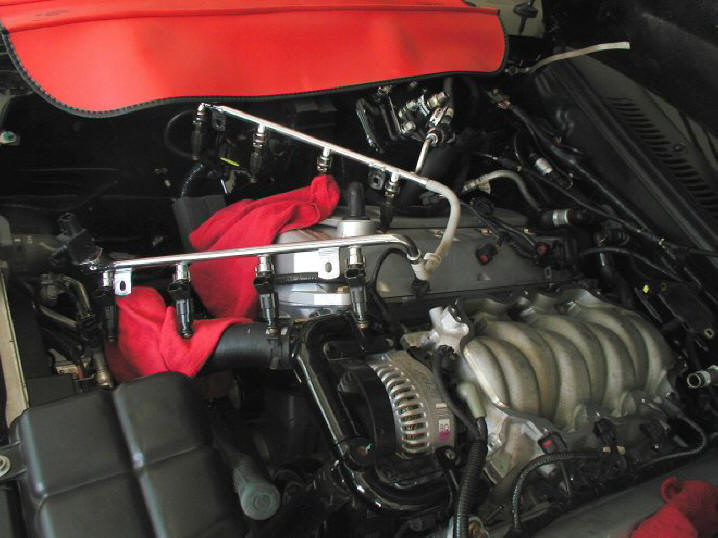
Here's a shot of the stock intake just prior to removal:
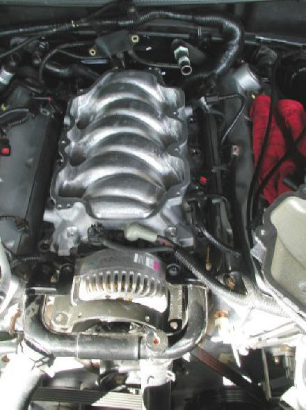
And here's a photo of the ported unit installed in place of the
stocker:
Finally, here's a shot of the engine bay after I had reassembled everything:
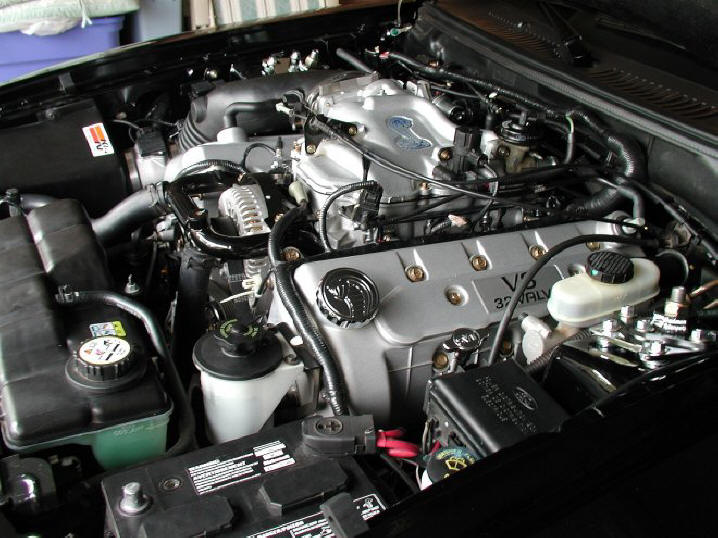
NOTE: Installation of the Kenne-Bell twin-screw kit
required the removal of this upgrade.
KB Big Oval Throttle Body
Before I ordered my Kenne Bell supercharger kit, I needed
to decide whether I was going to reuse the stock Cobra throttle body or swap it
out for the optional KB Big Oval unit. The decision had to be made
up front because the kit was available in two
different configurations, one with an
intake manifold designed to work with the stock throttle body, and another with
an intake designed for the Big Oval TB. I had been
concerned for some time about the limitations of the stock TB, even for an N/A
application, so as far as I was concerned, the choice was automatic. I went with
the Big Oval.
KB's Big Oval is manufactured by
Accufab, and
like all Accufab products, it's as much a work of art as it is an
automotive part. Here's a photo of the unit installed on the supercharger's
intake horn, prior to adding the air inlet tube. The blue tape covering the TB's
mouth is there only to prevent dust and debris from finding their way inside
during the supercharger installation.
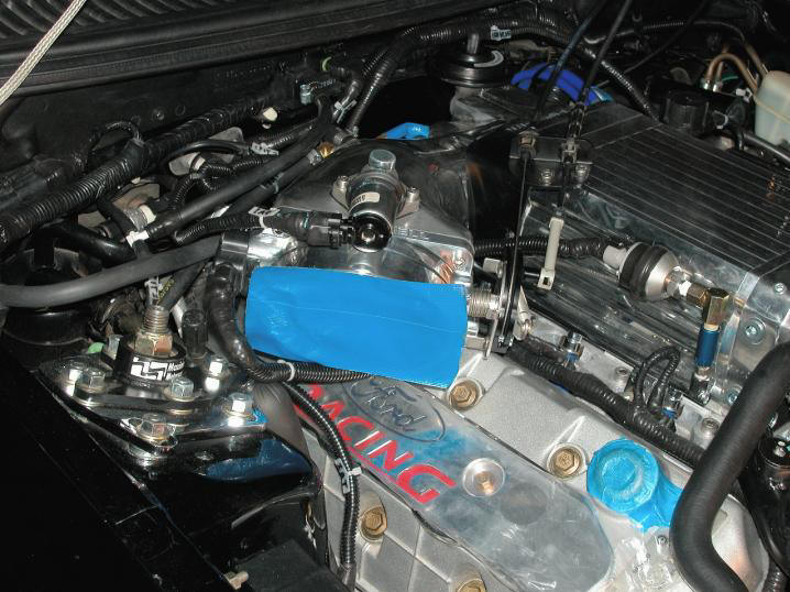
NOTE: The funky
appearance of the Ford Racing coil cover in the photo above is due to the
protective plastic, which I left in place during the twin-screw installation.
KB Cool Air Kit
The Kenne
Bell Cool Air Kit is an option for '99/'01 Cobra non-intercooled
supercharger kits, but is included with the intercooled kits. The
KB Cool Air Kit consists of a large 90mm MAF meter, a high quality,
flexible air inlet hose, mounting brackets, and an enormous K&N
cone-style filter, along with all the necessary adapters, sleeves, and
miscellaneous bits and pieces necessary to install it.
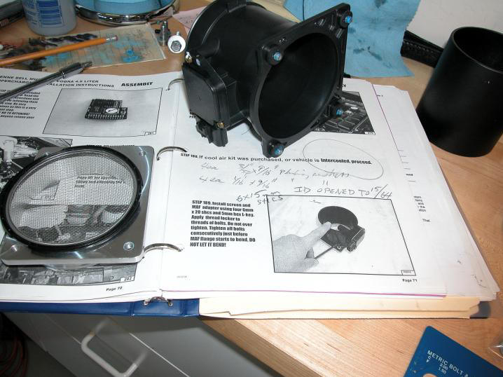
Here's a photo of the kit's MAF meter and its inlet screen just before
I installed them. After initially installing the inlet screen along with the
MAF, I removed the screen between the Cobra's first and second dyno sessions to
determine the amount of restriction
it imposed on intake air. The screen hasn't been
back on the car since that time. Does that tell you anything?
PCV Oil Separator
When my supercharger kit arrived, so did an intercooler that
bolted to the underside of the compressor's base plate, directly in the path of oil-laden
crankcase vapors. I decided that I needed to take steps to avoid a possible
disaster by preventing any oil that was being siphoned up through the PCV valve from reaching the intercooler's core.
I feared that if I didn't take preventative measures, the performance of the intercooler would gradually
deteriorate as it became increasingly
clogged with sludge, until it could no longer do its job effectively. Then, BOOM!
It took practically no time at all to find a
solution. In fact, a remedy was available from just about
any parts source, because the import crowd, which had long ago adopted forced
induction in lieu of raw displacement as a means of making more power, had
already been there and done that. Their solution consisted of nothing more than inserting a fluid trap into the
line between the PCV valve and the intake manifold. It was no-brainer simple, and it
completely eliminated the
problem as long as the trap was periodically emptied. Score!
Although countless brands and models of fancy billet canisters
are available, the basic concept is so simple that just about any tin can could
be modified to act as a catch tank. In fact, although I haven't personally
tried one, I genuinely believe that a resealed, empty soup can with a couple of
strategically placed 9mm barbed hose fittings
could do the job nicely. Of course, the commercially available billet catch tanks have much more
"bling" appeal than most old soup cans, not to mention
handy conveniences such as sight tubes and drain plugs, but those aren't
absolutely
necessary, and an old soup can would work. ...
The most important aspect of a properly constructed PVC catch tank
is that it will retain the closed system design that was engineered by the vehicle's manufacturer. Aside from its inlet and outlet
hose ports, a catch tank should be sealed. This means designs that include
little breather filters are to be AVOIDED! They'll throw off the
engine's management system and screw up the A/F ratio by allowing unmetered air
to enter the motor. I've seen so many poor catch tank designs and botched installations that
I sometimes wonder if I'm the only ratchet head who ever took the time to
study the design and operation of his PCV system. Allow me to reiterate:
it's a CLOSED
SYSTEM by design, and if you open it anywhere to unmetered air,
you've screwed up. Sure, you can tune around your screw-up - more
or less - but why create the issue in the first place?
Moving right along ... Having determined that both a drain
plug and a sight tube would be nice to have, and that a little bling appeal wouldn't hurt,
either, I perused the various catch tank offerings on eBay until I found one that fit
the bill for a good price and snapped it up. When
I received the tank a week or so
later, it arrived in a USPS mailer, sans original packaging or
documentation, and with two more threaded holes in its barrel than there were
fittings with which to plug them. The tank was accompanied by a pair of tiny
mounting brackets that
looked about as useful as tits on a boar and a short length of clear vinyl hose
that would have been more at home on a kitchen sink sprayer than in an automotive
engine bay.
Obviously, a few supplemental
purchases were in order. No worries. After I decided where
I would mount the little aluminum tank, a visit to my local Home Depot was all I needed to correct
most of the tank's deficiencies. I scored a length of galvanized stock, from which
to fab a functional mounting bracket, and a couple shiny new brass NPT caps to
plug the tank's two extra holes. I picked up the final item that I needed, a 10-foot length of
good quality rubber fuel
line, from a nearby Auto Zone.
TECH TIP:
The longer, the better where PCV hose length is concerned. Longer hoses
give PCV vapors a better chance to cool than shorter ones do, enabling more oil
to precipitate out of the vapor and reducing intake charge temperatures. For the
most effective setup, find a remote location in which to mount your catch tank,
rather than on the firewall, next to the PCV valve.
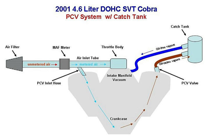
The PCV system layout on
an '01 Cobra includes two cam cover ports, one on the passenger side cam cover
for the intake of METERED air (air that has already passed through the MAF meter), and one on the driver side cam cover for
the discharge of crankcase vapors. The discharge side of the system is fitted with a check
valve (the PCV valve) to prevent any backflow of air into the driver side cam
cover when the intake
manifold isn't pulling a vacuum. By design, manifold vacuum PULLS air out
of the cam cover through the PCV valve. Vapors aren't forced out of the cam
cover under pressure. This means - obviously - that the PCV valve remains closed during WOT.
It is the PCV valve side of the system where you need to install
your catch tank, so it can intercept the
goop in the vapors coming from the crankcase. Just splice the tank in between the
PCV valve and the PCV vacuum port on the manifold. The valve must remain in the
system, and the catch tank should NOT be vented or fitted with a filter, since that
would open the system to unmetered air and skew your A/F ratio. Also, unless the
tank is internally baffled, its inlet and outlet fittings shouldn't be located directly
in line with one
another. Otherwise, crankcase vapors will just
short-circuit directly from the inlet to the outlet, compromising the tank's
effectiveness. Use the graphic below as a visual aid.
The intake side of your PCV system should remain unmodified. People are constantly doing stupid things
on this side. Some even rip out the PCV inlet hose, plug up its fitting on the
air inlet tube, and
stuff a
breather into the cam cover for fear of getting oil from the PCV system into
their intakes through their throttle bodies. Personally, I think that if these people
are seeing oil in their throttle bodies, either (1) they are over-oiling their
K&N air filters and that's the source of the oil, or (2) they have some
SERIOUS engine issues. Regardless, opening that end of the PCV system to atmosphere is not the solution. If oil
really is coming up out of the passenger side cam cover, this would be best
remedied by splicing a check valve into the PCV inlet hose, but I think the
likelihood of this situation occurring is pretty slim. The intake side of Taz's PCV
system remains unaltered and his TB never has oil in it.
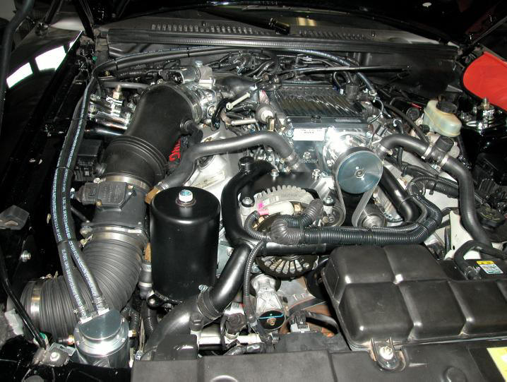
Below is a photo of Taz's engine bay with his catch tank system installed. In this photo, you can follow
the separator's inlet hose from the PCV
valve near the back of the driver's side cam cover all the way to the canister, near the prop rod on the passenger side of the engine bay.
From there, you can trace the tank's outlet hose to the 9mm PCV vacuum port on
the KB intake manifold, near the center of the firewall. Note that the tank's
two hose fittings are side by side, rather than in line with one another. This
forces crankcase vapors to execute a 180-degree turn between the inlet and
outlet, slinging the relatively heavy oil/water droplets off during the
process. It's a very simple, but effective arrangement.
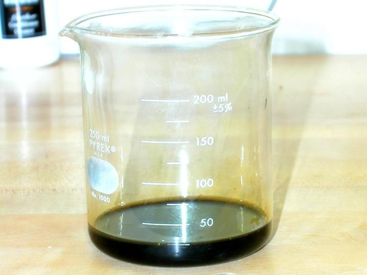
Does the catch tank work? You bet your gluteus maximus it does.
Here's a look at the amount of goop I pour out of my tank every 3,000
miles or so. Meanwhile, my intake and the intercooler's plates remain dry. Without the catch tank intercepting this nasty stuff,
it would be building up on my intercooler's core.
The installation of a PCV catch tank system on a New Edge
Mustang really is a very straightforward procedure. Don't make it into anything
complicated, because it isn't. Just splice a tank with inlet and outlet ports
into the hose between the PCV valve and the intake manifold. That's it.
Editorial Comment:
Many folks run breathers on their cam covers as a means of
keeping oil out of their intakes. How lame is that? A decent catch tank is no more expensive
than a pair of breathers, does just as good a job at keeping blowby goop out of
the motor's intake, AND a catch tank system prevents carcinogenic hydrocarbons from escaping into
the atmosphere, not to mention into
YOUR OWN passenger compartment.
For your own sake, if for no other
reason, you should use a closed-system catch tank, not breathers.
But hey, if you want to die of lung cancer in 10 or 20 years, be my guest. Death
by stupidity isn't exactly a novel concept.