![]()
![]()
![]()
![]()
![]()
![]()
![]()
![]()
![]()
![]()
![]()
![]()
![]()
![]()
![]()
![]()
![]()
![]()
![]()
|
|
|
|
Instrumentation Upgrades
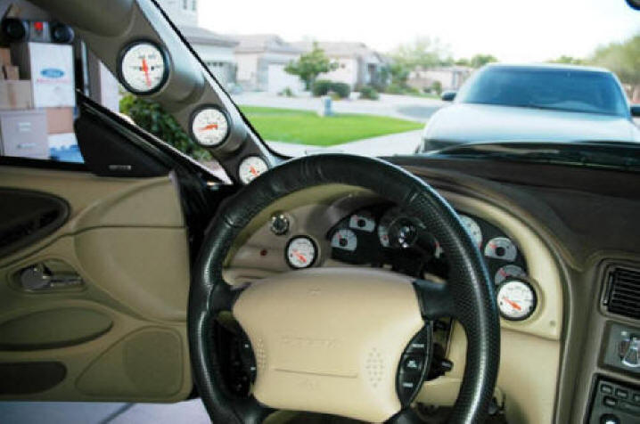
By the end of 2008, Taz's miscellaneous electrical upgrades had become so extensive that this page was very slow to load due to the abundance of graphics it contained. To alleviate the problem somewhat, I moved all of Taz's instrumentation upgrades, which previously had been included here, to their own page. The Cobra's instrumentation tweaks had become extensive enough by then to warrant a page of their own, anyway. You can now read about the car's instrumentation upgrades by clicking either the hyperlinked text or the photo below.
Jump to Instrumentation Upgrades page
MAFterburner+
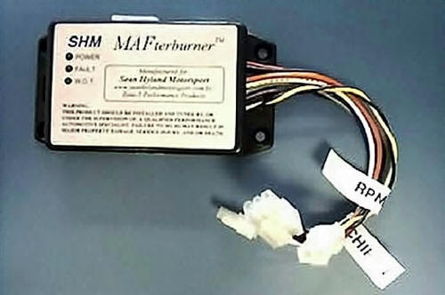
After I bolted my ported intake in place in 2002, the car ran for only a few days before throwing diagnostic trouble codes (DTC's) indicating lean conditions in both banks. The Cobra's powertrain control module was apparently unable to compensate for the increased flow of the ported intake coupled with the C&L MAF meter's poor calibration at low flow rates. Luckily, I already had a remedy for this little problem sitting on a shelf in my garage. All I needed to do was to install it. Mark Chiappetta at Zone 5 Performance had developed a device for tweaking a car's fuel trims, and I had picked up one the units during a group purchase. The so-called MAFterburner was capable of effectively manipulating any MAF meter's transfer function, and it was delivered with Windows-based software that enabled graphical adjustment of the fuel trims at multiple points across the engine's RPM range. Here's a stock marketing photo of a MAFterburner for reference. Sorry about the image quality, but it was lifted from an Internet site.
A few PCM wiring harness modifications were necessary to splice the MAFterburner into the vehicle's MAF sensor circuit. But thanks to excellent documentation, installation of the unit was a snap.
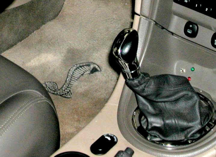
I had purchased the "Plus" version of the MAFterburner (later renamed the "Stage-2" model), which supported two different sets of fuel trim calibrations, so a bit of additional wiring work was required to provide trim switching capability and visual indication of which tune was active. I decided to mount a mini-toggle and a pair of LED's in a blank spot on the trim panel at the base of the center stack. Here's a shot of the MB+ wiring ready for installation of the modified trim piece. (This photo also shows the forged handle of the Steeda Tri-Ax short throw shifter that had replaced the TR-3650's stock unit at some point along the way.)
The MAFterburner did the trick. Once I had applied the appropriate tweaks to the MAF meter's transfer function, the PCM was perfectly content, and the DTC's never again returned. Here's a shot of the finished work. In this photo, you can see the Momo "Cobra" shift knob that was installed at that time.
I left the MB+ in place after removing the ported intake and C&L MAF meter to install the car's twin-screw blower kit, but I reconfigured its operation. One program in my MAFterburner is now configured to provide ZERO compensation for both closed loop and open loop PCM operation. When this program is active (most of the time), the engine's fuel management system operates as if the MB+ weren't in the circuit at all. The second program is configured to lean out only the open loop A/F ratio by a few points across the board to provide a custom "shootout" mode for use with racing fuel. (Closed loop compensation remains zeroed out, even in shootout mode.) It's nice to be able to instantly toggle from one program to the other with the flip of a switch. Maybe, I'll test the effectiveness of this capability one of these days during a dyno session, so I can quantify the performance improvement that it provides. Maybe not. NOTE: The MAFterburner unit is no longer in production. It was probably discontinued because its functionality has been incorporated into the plethora of handheld tuners that have flooded the market in recent years. I continue to use mine, because I don't want to risk compromising the Kenne Bell tune that has been programmed into my performance chip, and my MB+ enables me to make adjustments to my A/F ratio without changing anything in either the chip or the PCM.
Black Box II
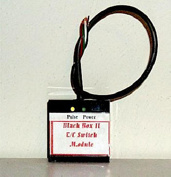
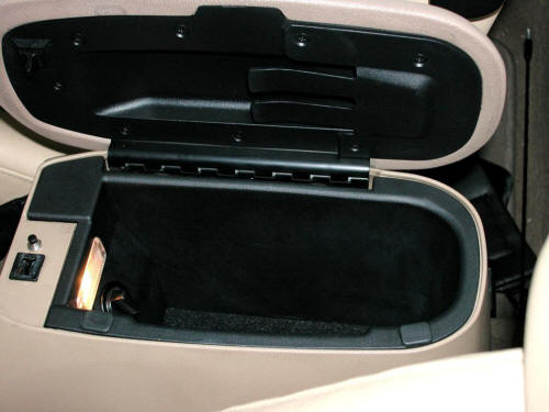
To placate the Safety Nazis, Ford engineered the Cobra's traction control circuitry to revert to ON every time the car is started, regardless of its previous setting. This is accomplished through the use of some simple digital logic circuitry. The pushbutton switch in the center stack does nothing but pulse a digital flip-flop to toggle the T/C off or on. While I agree that traction control assistance has its place, and that it can be very useful in certain adverse conditions, I also believe that it hinders performance by retarding ignition timing whenever the rear tires break loose. I almost always wanted the T/C off, and after the supercharger installation, it became vitally important to ensure the T/C circuit was de-energized most of the time. Remembering to manually disengage the nanny circuit had always been a nuisance, and I forgot more often than I remembered. But I eventually stumbled across a handy little device that made life with my traction control nanny much easier. The little unit, appropriately named the Black Box II, automatically restores the T/C circuit to its previous setting, rather than defaulting to ON, each time I start the car. Installation was very straightforward, and the unit now resides quietly inside Taz's console, near the T/C switch. SCORE!
If you're interested in one of these, R and R Specialty Auto Electronics offers a similar unit.
HID Bi-xenon Retrofit Project
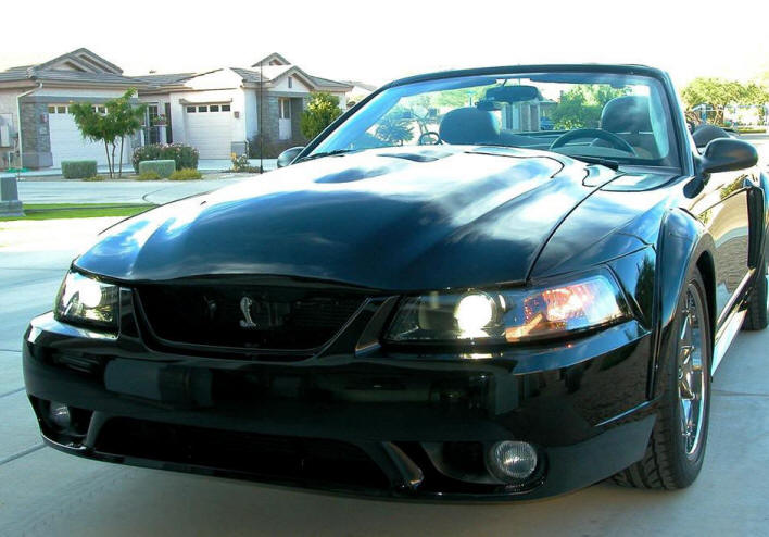
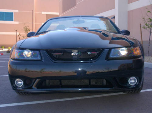
Several years ago, I became fascinated with the prospect of retrofitting the Cobra with HID headlights. Not one of the "Glare Monster" kits that provide only rebased HID light sources for use in unmodified OEM headlamp housings, but a genuine OEM-quality lighting system. Since the Corbra's factory headlights employ the same dual-filament 9007 halogen bulbs for both high and low beam functions, I wanted an HID solution that would also handle both. I spent nearly two years studying the feasibility and considering my options before I finally turned my fantasy into reality in 2005. During my research, I had discovered that a few small companies - mostly garage operations - were willing to modify stock halogen headlamp housings as required to accept genuine OEM projector systems - for a price. (Read NOT CHEAP!) Despite the high cost, I decided that it was in my best interest to have one of these experienced craftsmen provide me with a solution, rather than trying to shoehorn a pair of bi-xenon projectors into a couple of stock housings on my own, so I sent my money, along with a pair of fresh housings, off to one of these companies for the retrofit. Apparently no one had ever before accomplished a bi-xenon retrofit for a New Edge Mustang before mine. There had been a few single xenon (low beam only) projectors stuffed into '99 - '04 'Stangs, but to the best of my knowledge, mine represented the first successful bi-xenon project for one of these cars. Even my retrofitter, despite having successfully completed scores of projects for other vehicles, almost threw in the towel more than once, but he eventually persevered. (Kudos to Sean for finally pulling it off!) Since that time, smaller bi-xenon projector assemblies have made the task considerably easier, and many others have now followed suit. Three months after I initiated the process, the first pair of New Edge Mustang bi-xenon HID headlights arrived at my doorstep, complete with plug-and-play wiring harnesses. Of course, being the anal-retentive perfectionist that I am, I wasn't entirely satisfied with the as-delivered solution, so I performed a bit of cleanup work on the lights. Then, I fabricated my own custom harnesses and control boxes from scratch, and since I couldn't come up with a suitable mounting arrangement for the supplied Denso ballasts, I replaced them with a pair of Philips model LVQ212 units and custom brackets. After countless hours of hard work - not to mention a few hundred more shekels - I finally had exactly what I wanted. The finished project is pictured in the photo below.
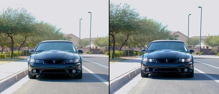
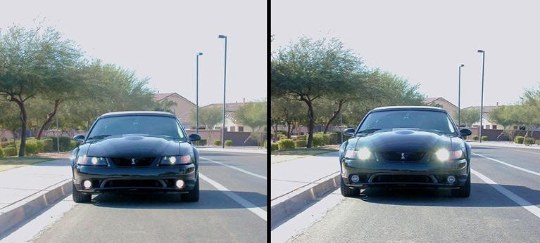
Download the PDF file linked below for a pictorial chronicle of my efforts. One of these days, I may get around to fleshing out the photos with some text. Or not. Meanwhile, if a picture is worth a thousand words, you'll have more than enough to figure out the details. This PDF is BIG, so you may want to right-click the link and select "Save Target As ..." or "Save Link As ..." to save a copy to your own computer. Bi-xenon HID project photos (very large PDF) The series of photos below will give you at least some idea of the difference in lighting quality between my HID retrofits and either the stock halogen lights or one of those nasty HID kits. For reference, the car is pictured at the top left with its lights off. At the top right, the car is shown with its low beams energized. In the bottom row, you can see the way the car looks with both the low beams and the fog lamps on, followed by a shot of the car with the high beams energized.
The projectors in my headlamp housings are Hella units, specifically the same units with which European-spec Audi A6's were fitted at the time. Although I could have selected DOT-spec projectors, I opted for ECE (Euro-spec) units, because I prefer their sharper cutoff characteristics. As shown above, the difference between the low and high beam patterns of these lights is enormous. The low beam pattern is very subdued, and although they light city streets very well, the low beams are never objectionable to oncoming drivers. The high beams are a completely different matter. They'll burn out the retinas of approaching drivers from quite a distance if I inadvertently leave them on. Editorial Comment: Because the light dispersion of rebased HID bulbs installed in stock halogen reflector headlamp housings is uncontrolled, those setups invariably look like high beams to oncoming drivers. The glare they produce can get you shot in some places, and not a moment too soon, as far as I'm concerned. Additionally, the light produced by rebased HID lighting kits is worse than no light at all in heavy fog or rain, because all that scattered light bounces right back into your face. This characteristic is also the primary reason that, from a functional standpoint, HID light sources should never be installed in fog lamp circuits. They'll dazzle you blind in foggy conditions. Let's be clear on this. If you install rebased HID bulbs in any sort of halogen reflector housings simply because you think they look cool at night when you're gazing admiringly at your car from the side of the road, you're a MORON, pure and simple. Clear enough? Your headlights were put there to help you see down the road in the dark. HELLO! They are NOT there for decoration, self-expression, or artistic interpretation. When you decrease the ability of your lights to do their jobs, you're demonstrating a complete absence of intelligence. And when you callously blind oncoming drivers in the process, you're making a public menace of yourself. Make no mistake about it. The only way to actually improve your vehicle's lighting performance, rather than making a complete ass - not to mention first-class annoyance - of yourself when switching from halogen to HID lighting is the way I and others like me have done it. You must transplant an entire OEM HID system into your car. A cheap plug-n-play HID kit will NOT improve your vehicle's lighting performance. It can't, because it cannot defy the laws of physics. QED Another characteristic of my lights that is obvious in the photos above is their color temperature. My HID bulbs are very close in color temperature to the color temp of the Sylvania Silverstar halogen bulbs in my fog lamps (4300K for the HID's vs. 4100K for the Silverstars). This is the same color temperature that all auto manufacturers use for their original-equipment HID systems, which makes sense, because this color provides the best illumination. Period. Bulbs closer to the blue/violet end of the color spectrum provide less effective lighting performance. Since my motivation for this project was to improve my ability to see down dark roads at night, I wasn't about to shoot myself in the foot by installing the wrong color temperature bulbs. Editorial Comment: While blue/violet headlights may look "cool" to some folks (primarily the Clearysil set), they're grossly inferior from a lighting standpoint. Anyone who knows anything about lighting is aware of this, so how do you think idiots sporting blue/violet headlights look to any informed observer? That's right. Just like the retards that they are. How "cool" is that? Dual beam halogen bulbs, like the 9007's with which Taz was originally equipped, contain two different filaments, so switching between their high and low beam patterns was as simple as energizing one set of filaments or the other, but switching between high and low beams is performed differently with bi-xenon HID lights. High-voltage gas discharge lights don't take kindly to being rapidly switched on and off, such as in a "flash to pass" situation, and this can quickly destroy the ballasts. Since they can't be quickly toggled on and off like lamps with filaments, bi-xenon HID's employ a solenoid-actuated cutoff shield to accomplish the change in beam pattern. For low beam operation, the solenoid is de-energized, and the shield blocks light above the cutoff level. Switching to high beams energizes the solenoid, which pulls the cutoff shield away from the light sources. The solenoids are rigidly mounted to the projector frames, along with the bulb sockets and optics, and each solenoid is equipped with a two-wire (Hella) or 3-wire (Bosch) harness for connection to the vehicle's headlamp dimmer switch circuitry. Some of the plug-and-play HID headlight kits that rely on rebased bulbs attempt to provide both high and low beam functionality with what are often called "wiggle lamps." These kits claim to be bi-xenon, but they are not, because they don't implement high/low beam functionality as described above. Rather than being rigidly secured in their bases, the bulbs are allowed to pivot up and down, and electro-magnets are employed to shift their positions. The term "wiggle lamps" is certainly appropriate here in more ways than one, because that's exactly what you get in lighting performance, as well as lamp construction. Since these bulbs aren't rigidly mounted in the vehicle, the beams they throw are continually bouncing all over the place. Great for disco parties, but not so hot for driving in the dark! Another difference between HID's and halogens that is worthy of note is that the actual operating current requirement of HID headlights is much lower than that of halogen lamps. Then, why the need for relays and heavy gauge wiring with HID's? Simply put, gas discharge lighting systems employ devices called igniters to fire up their light sources, and these igniters draw quite a bit of current while energized. Although the duration of this high current demand is brief, the addition of relays and stout wiring to power the ballast-igniter units is strongly recommended to avoid deterioration of the OEM headlight wiring. TECH TIP: In Generation III HID headlamp systems like mine, the bulb igniters are built into the ballasts. This limits ballast mounting options, because the high-voltage cable between each ballast and its light source must be kept as short as possible to minimize voltage drop, as well as noise that could interfere with the vehicle's ignition and other systems. In the newer Gen IV systems, the igniters have been relocated to the backs of the bulb connectors in order to provide more ballast mounting flexibility, but this adds to the amount of clearance required behind the headlamp housings. There may be insufficient clearance behind the housings in a New Edge Mustang to accommodate the Gen IV system's topology, so be cognizant of which type you're buying if you're thinking about installing a retrofit system. 2014 Update: Although Taz's projectors continued to perform flawlessly nine years after their installation, I became curious about the performance of the recently introduced LED emitter kits for the stock reflector housings. Since I still had my OEM headlamp housings stashed away in storage, converting to LED's would be a simple procedure if they offered even better lighting performance than my HID projectors. The low-beam glare from LED's is reported as being less objectionable to oncoming drivers than that produced by the HID plug-and-play kits, which is certainly a move in the right direction. However, it appears the LED kits suffer from the same inadequate high-beam throw that plagues rebased HID's installed in stock reflector housings. In other words, while they light nearby objects well, their ability to illuminate distant objects is substandard when compared to even OEM halogen bulbs, as this candid report from one early adopter states: "The only disappointment is high beams. The bulb definitely gets super bright if you're looking at the front of the car but for the driver of the car the difference is hardly even noticeable. We hit a couple of pitch dark back roads that have no street lights and were approaching a hill in the distance. Flipping between high beams and low beams made almost no difference and we couldn't see the hill till we were there. Stock high beams would have cast some light." This being the case, Taz will continue to rely on his HID projectors to light the way, at least for now. The throw of the Hella projectors is flawless in both high- and low-beam modes, and their ECE-spec cutoff patterns are razor sharp.
FRPP Speedometer Recalibrator
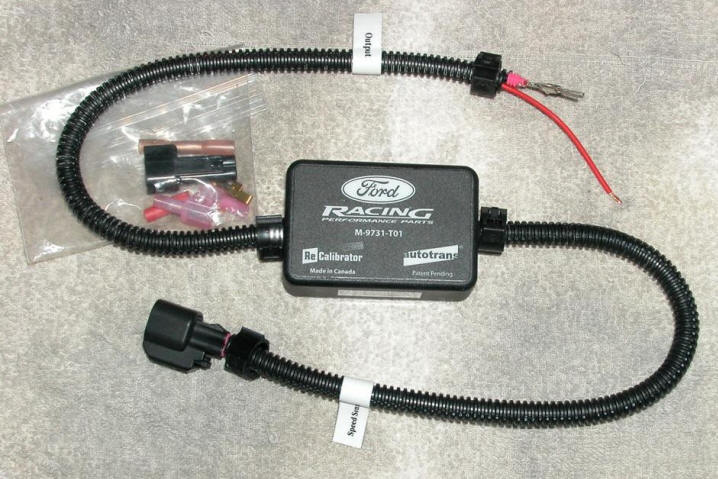
When I performed Taz's 2006 - 2007 drivetrain upgrades, I also installed a Ford Racing speedometer recalibration unit to compensate for the change in overall gearing and restore the accuracy of the car's speedometer. I found a ledge inside the base of the center stack where I could stash the little unit and still remove it again later to recalibrate for future gearing or tire diameter changes. The unit I originally purchased for installation is depicted below, but this turned out to be the wrong model for a Ford Racing '00R T-56 (Tremec # TUET-1260).
The unit pictured above would probably work fine for a takeout transmission from a Terminator Cobra, but it is equipped with the wrong OSS (Output Shaft Sensor) connector for the '00R T-56. It seems the 2000 Cobra R's transmission uses the 1999 style connector, rather than the 2001 and newer style. The correct unit, FRPP # M-9731-T99, looks identical to the one pictured, except for the connector. Inside the little plastic case, in addition to the requisite electronics, is a bank of DIP-switches that can be adjusted to provide whatever percentage of compensation is required to produce an accurate speedometer reading at the gauge. If you have one of these little gems, and you need a copy of the DIP-switch chart, you can find one here: FRPP Recalibrator DIP-switch Chart To enable the unit's OSS harness to reach the transmission from the case's resting spot in the center stack, I created a passage in the metal baseplate of the outer shifter boot. This same portal also accommodates the power circuit for the T-56 transmission's REVERSE solenoid. Both circuits are diagramed in the PDF file linked below. T-56 speed calibration & reverse solenoid circuits
Reverse Solenoid Circuit
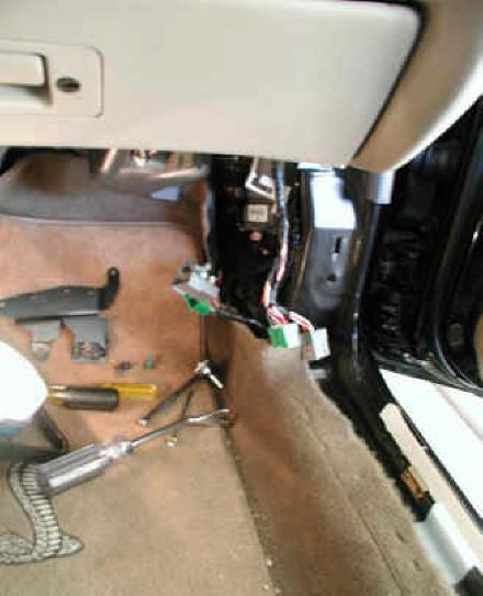
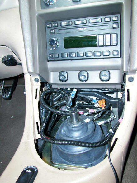
When I installed the Ford Racing speedometer recalibrator, I also designed and installed a switched power circuit for the REVERSE solenoid of the T-56. (Since the car's OEM TR-3650 hadn't been equipped with a reverse lockout, the car possessed no such circuitry.) Many who retrofit their vehicles with T-56 transmissions simply tap into the brake light circuit to activate the solenoid whenever the brake pedal is depressed. This is a quick and easy solution, but I wanted more positive control over exactly when and how long the solenoid was energized. Others install console or dash mounted switches, but those either make engaging reverse a two-handed operation or they employ maintained contact switches that must be manually deactivated. I wasn't especially keen on either alternative. I wanted positive control and single-handed engagement of reverse without having to remove my hand from the shifter. Eventually, I realized that I wanted a shift knob with a momentary contact pushbutton, so that's route I chose, even though this meant cramming even more wiring into the console. All the circuitry that I've stuffed into the base of the center stack over the years, combined with all the factory wiring already there, has made that area quite crowded, but using flagged tie-wraps has enabled me to keep everything sorted out when I need to get inside there for any reason. To give you an idea of what I'm talking about, here's a picture that will make your head hurt.
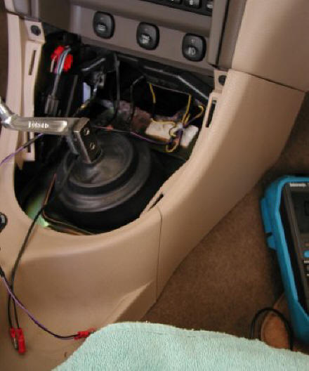
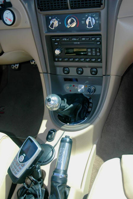
I had seen various shift knobs that were factory-equipped with momentary contact pushbuttons. Using one of those to control the reverse solenoid would have quickly and easily provided the functionality I was after, but none really suited me from a aesthetic perspective, so I decided to fabricate my own custom solution by installing a button into a Momo knob that matched my E-brake handle. After I had obtained a suitable candidate, accomplishing the necessary modifications required considerable time and effort, but I had exactly what I wanted after I had finished. TECH TIP: Every shift knob that employs set screws to secure it to the shifter handle invariably sits cockeyed and continually requires retightening. The Momo knob was no exception. However, I have devised the perfect fix. First, throw the set screws in the trash. Then, pick up the correct diameter ASTM plastic tubing at your local Home Depot and press it into the neck of the shift knob (5/8" OD was the right size tubing for mine). Finally, after you have pressed it into place, tap the inside of the ASTM sleeve with the correct thread for your handle. This transforms the knob into a threaded design that rests level on your shifter handle and doesn't need to be retightened every few days. Many Momo shifter boots are equipped with threaded collars, enabling them to be screwed onto the bottoms of most Momo shift knobs, such as the one I selected for this project. Availing oneself of this capability produces a very integrated, upmarket look. I did this when installing Taz's new shift knob, and since I had routed the wires for the reverse solenoid circuit directly out the bottom of the knob, inside the perimeter of the boot's collar, the circuit's wires are invisible when everything is buttoned up. The only wires visible in the photo below are the cable for the OEM audio system's AUX Input signal, which I kept handy to enable quickly switching between my satellite receiver and MP3 player, and the SIRIUS receiver's power and antenna leads, which are connected to its cradle. All those were subsequently removed when I installed my aftermarket in-dash unit and optional satellite radio modules. (That project is detailed farther down this page.)
To provide a visual cue that the reverse solenoid is energized, I installed an amber LED in the REV circuit. This LED is visible in the above photo, just to the right of the 'R' on the T-56 shift placard that I also added to the base of the center stack. Although this circuit is very simple and straightforward, I included it in the diagram that I created for the Ford Racing speed calibration unit circuitry, because I diligently document all electrical system modifications to facilitate troubleshooting if/when necessary later. Click the PDF file linked below if you'd like to see this circuit. T-56 speed calibration & reverse solenoid circuits
Telemetry Upgrades
I must confess to being the poster child for the dreaded "Driver's Lead Foot Disorder." Naturally, to minimize the financial impact of this terrible affliction, I have always endeavored to protect myself with capable "Cops & Speeders" defensive gear. An Escort radar detector was my very first aftermarket acquisition for the Cobra, way back in 2001. Over the years, as the traffic enforcement industry has escalated its efforts, and Escort has responded with improved models and an expanded arsenal of defensive weapons, I have updated the car's speed enforcement telemetry accordingly. To help keep my driving record respectable and my insurance rates low, Taz is now equipped to defend against both RADAR and LIDAR. I have the placed details of this equipment on a separate page to reduce the size of this one and the the time required to load it . You can read about the car's complement of RADAR-LIDAR countermeasures by clicking either the photo or hyperlinked text below.
Jump to Telemetry Upgrades page
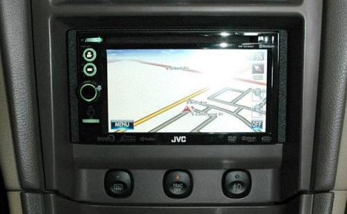
Media and Nav Equipment Upgrades
Over the years, Taz's media equipment has undergone multiple rounds of upgrades, large and small. Along the way, I even added navigation capabilities to the system. As a matter of policy, I have retained of record of each project. Eventually, these various modifications required a page of their own. Clicking either the photo or the hyperlinked text below will take you to the page containing the details of these projects.
Courtesy Lighting Project
By the time Ford's bean counters had finished “decontenting” all the New Edge Mustangs, the cars were left with a nearly complete lack of courtesy lighting. This graced every single one of them with the ambience of a mid-60’s stripper or 70's econobox, and being forced to fumble around at night for something in one of Taz's dark or poorly lighted areas was a continual irritation to me. I put up with this shortcoming for over a decade, while I focused on more important upgrades, but Taz was well enough sorted out by 2013 for me to do something about it. Click the photo or the hyperlinked text below to jump to a page containing all the details of this project.
Jump to Courtesy Lighting project page
|